LED Disco Ball That Responds To Music With Arduino ESP32
I have always wanted to create some sort of display that responds to music, and this final project for my Creative Embedded Systems class seemed like the perfect opportunity! I decided to create a disco ball-inspired LED display that responds to music. To do so, I put an LED strip into clear piping, shaped the piping into a sphere-like shape, and connected the LED strip to an ESP32 and a microphone. Using the data from the microphone, the LED strip lights up in different patterns.
View this project on my GitHub
MY PROJECT
MATERIALS
- Arduino ESP-32 TTGO T-display like this one
- USB-C cord (make sure that your cord supports data transfer, not just power– see more about that here. For this project, you will use this cable both to upload code to your device during development and to power the device once it is finished.)
- Microphone (I used the Arduino Sound Sensor)
- Breadboard (this isn’t actually necessary, but very helpful for prototyping and troubleshooting your project!)
- 5V Battery pack
- LED Strip (I used this one)
- Clear flexible tubing (encloses the LED strip)
- Hearty wire and wire cutters (needs to be strong enough to hold the flexible tubing in the spherical shape– I used wire about 4mm thick, similar to this one)
- Xacto knife
- Arduino IDE download here
STEPS
1. Setting up the hardware
My first step for this project was connecting my various forms of hardware and ensuring that they worked. My LED strip had female wire connections for ground, power, and data, and it also had two loose, unstripped wires that could serve as connections for ground and power. I used a wire to connect the data connection to the ESP32, but I opted not to use the ESP32 to power the LED strip because of the strain that that amount of power would put on such a small device. Instead, I stripped the loose ground and power wires and soldered them to the ground and power wires of an external battery pack. I used heat shrink to protect the soldering.

Once I had successfully connected the LED strip, I connected the microphone. The ESP32’s power source was plenty to power this small microphone, so I connected the ground, power, and analog data outputs to the ESP32 directly. I used the analog output from the microphone even though I ultimately converted it to a digital format (either the LED strip is “on” or “off”) because I wanted to be able to define where the line was between “on” and “off” myself, and I was able to do that by using the analog output.

To power the ESP32, I used the USB-C cable plugged into my laptop. I opted not to use a battery pack here because although it restricts the mobility of the project, using the battery pack for both the ESP32 and the LEDs would run the battery pack out of power too quickly.

2. Writing the code
My code reads output from the microphone describing the change in volume over 200 milliseconds, decides if that change in volume is significant enough to suggest that it was triggered by a beat in the music. If the code interprets the change in volume as a beat, it invites the disco ball to flash off, creating a visual representation of the beat. Simultaneously, it also rotates through many different colors, in order to make the flashing of the disco ball more visually interesting.
Check out my code at a more in-depth level on my GitHub!

3. Creating the enclosure
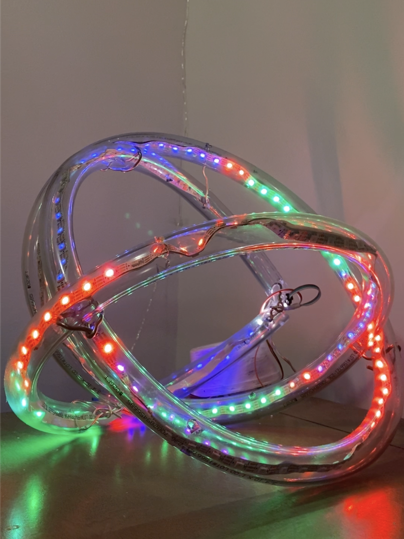
Once I had completed the software and hardware, I created my enclosure out of clear flexible tubing and wire. I used an Xacto knife to cut holes in the tubing into which I could insert wire to create joints to hold the shape together.

By using these joints, I created a spherical shape that mirrored the shape of a real disco ball. I also added a hook on top of the disco ball so that it can be hung from a ceiling.

The hardware here is hidden behind the small plastic dish, which both protects them from damage and from view! This was a part of my enclosure that I added at the end, mostly for aesthetic purposes.
4. Final product
Finally, once my enclosure was finished, I took a video of my final product, which you can see below! The disco ball successfully lights up according to the beats in the music, and I couldn’t be happier with my results!
Just for fun, here’s another video from when I was testing out different music– in this one, I’m clapping, because the beats in this music weren’t distinctive enough for my device to pick them up!
CREDITS
This project was completed for Module 4 of Mark Santolucito’s Creative Embedded Systems course at Barnard College. See more about the assignment and his work on his website here!